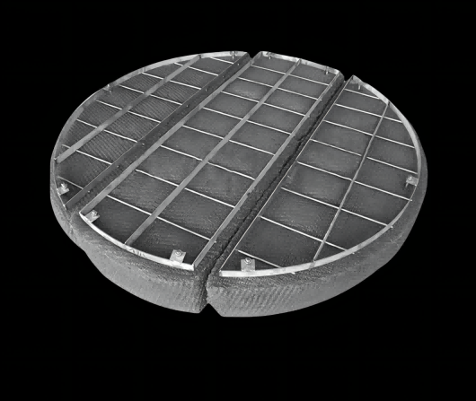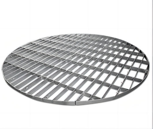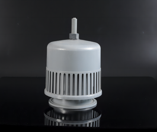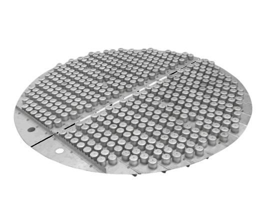

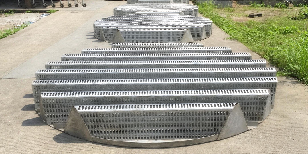
Figure 1: Camel hump support grid — continuous arched profile stamped from steel plate.
Engineering Alert: The support grid is the foundation of your packed bed. A failed support means collapsed packing, blocked gas flow, and a costly shutdown. Camel hump (camelback) grids deliver 90%+ open area with exceptional load-bearing capacity—but only when designed to your specific column loads. Here's the data you need.
A camel hump support grid—also called a camelback support—is fabricated from steel plates stamped into continuous arched (wave) profiles. The "humps" create a rigid structural section, while the spaces between arches provide high open area for gas and liquid passage. Unlike flat bar grids, the arched geometry turns each rib into a load-carrying beam.
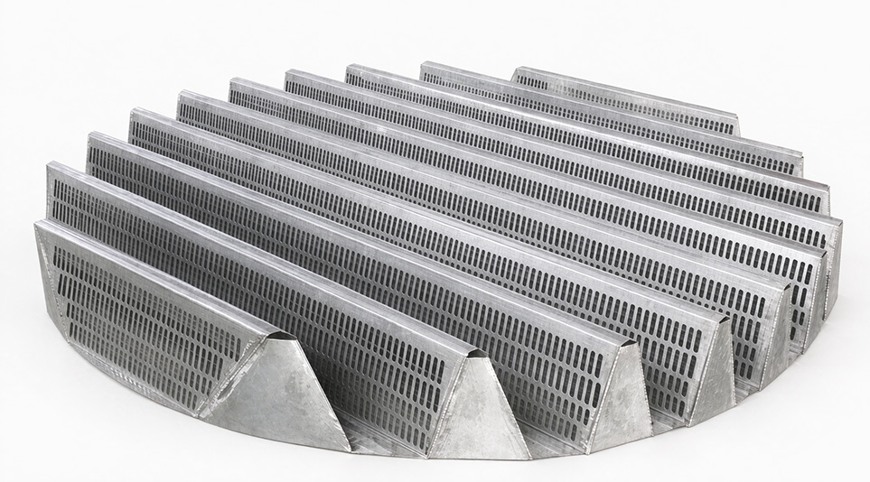
Figure 2: Key dimensions—arch height (H), plate thickness (t), and open area ratio.
| Parameter | Typical Range | Design Note |
|---|---|---|
| Open Area | 90 - 95% | Minimizes pressure drop across the support plane. |
| Arch Height | 150 - 300 mm | Higher arches carry more load but reduce bed height. |
| Plate Thickness | 3 - 6 mm | Driven by calculated bed load (see Section 3). |
| Module Width | 300 - 500 mm | Must pass through the column manway (typically DN500 or larger). |
| Hole Diameter | 10 - 25 mm | Balance liquid drainage vs. packing fallback. |
The load-bearing capacity of a camel hump grid depends on three variables: plate thickness, arch height, and material grade. The total bed load includes packing weight, liquid holdup, and any process-side pressure differential.
Typical Load Capacity by Plate Thickness (SS316L, Arch Height 200 mm):
Design Safety Factor: Always specify a minimum 2.5× safety factor over the calculated operating load. Temperature above 300°C requires derating—consult our engineers.
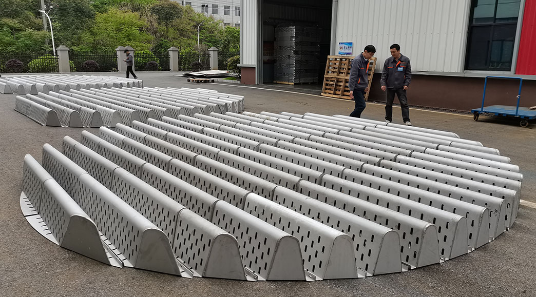
Figure 3: Camel hump grid (left) delivers 90%+ open area vs. ~45% for a traditional bar grid (right).
| Factor | Camel Hump Grid | Bar Grid |
| Open Area | 90 - 95% | 40 - 50% |
| Pressure Drop | Minimal | Moderate to high |
| Liquid Redistribution | Built-in (arch valleys collect & re-drip) | None (requires separate collector) |
| Load Capacity | High (arch acts as beam) | Moderate |
| Fouling Risk | Low (self-draining valleys) | Higher (flat surfaces trap solids) |
Step 1 — Calculate Bed Load: Packing bulk density × bed height × tower area + liquid holdup (typically 5-15% of packing volume). For 500Y packing, expect ~7.2 kg/m² per mm of bed height.
Step 2 — Verify Manway Access: Module width must be ≤ manway ID minus 50 mm clearance. Standard DN500 manway → max module width 450 mm.
Step 3 — Check Process Conditions: Temperature > 300°C requires thicker plate or upgraded alloy. Vacuum service needs smooth gas entry (hump profile minimizes entry loss).
Step 4 — Match Corrosion Rating: Same alloy as your packing. See our 304 vs 316L guide for chloride thresholds.
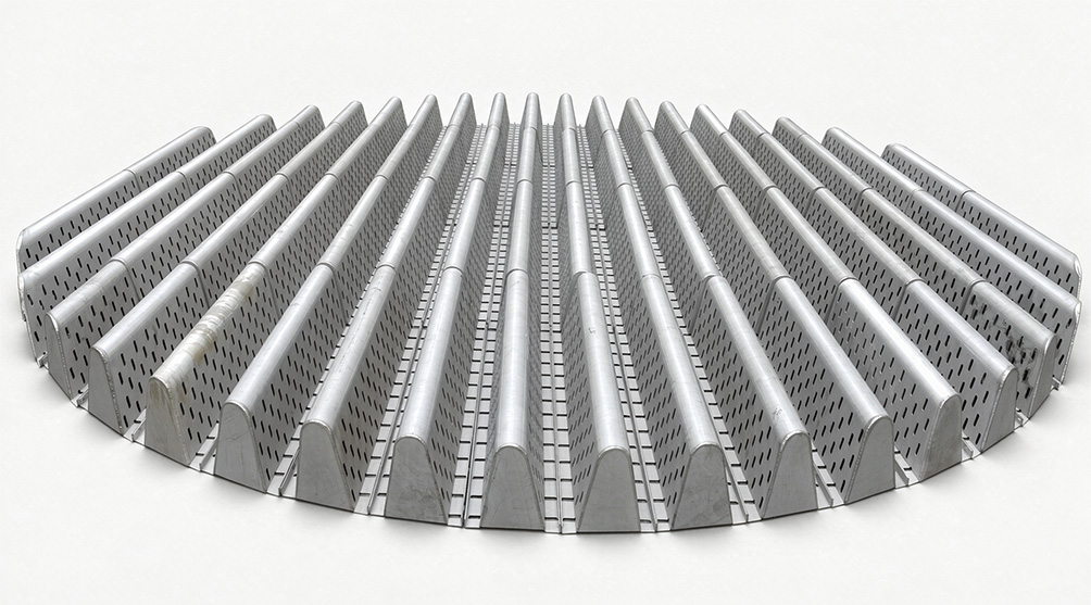
Figure 4: Installing camel hump grid modules through a DN500 manway.
| Failure Mode | Cause | Prevention |
| Permanent Deformation | Overload or high-temperature creep | Apply 2.5× safety factor; derate for T > 300°C |
| Packing Fall-Through | Hole diameter too large for packing size | Max hole = 60% of packing corrugation spacing |
| Gas Bypassing | Gaps between modules and shell | Weld perimeter seal strips during installation |
| Corrosion Perforation | Concentrated corrosives in valleys | Specify same alloy as packing; ensure drainage |
The camel hump grid sits at the bottom of the packed bed. Above it sits the packing, and above that sits the liquid distributor. The grid's arch valleys naturally collect liquid and act as a crude redistributor—especially valuable when paired with perforated plate structured packing, which adds lateral redistribution through perforations. For a complete overview of packing selection, see our 5-factor guide.
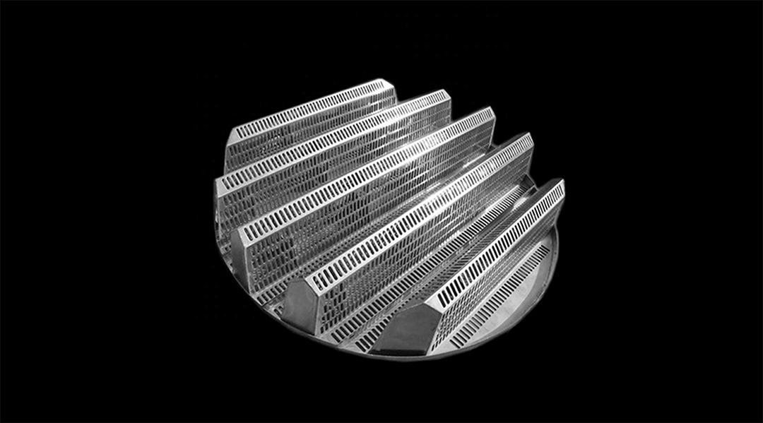
Figure 5: Full tower internals assembly—camel hump grid at bottom, structured packing in middle, liquid distributor on top.
Q: Can a camel hump grid replace a separate liquid collector?
A: In many cases, yes. The arch valleys collect liquid and drip it onto the bed below, providing basic redistribution. However, for tall columns (> 6 m bed height) or severe maldistribution, a dedicated liquid collector and redistributor is still recommended at intermediate levels.
Q: How do I prevent packing from falling through the grid holes?
A: The maximum hole diameter should not exceed 60% of the packing's corrugation spacing. For 250Y (spacing ~25 mm), holes should be ≤ 15 mm. For 500Y (spacing ~12 mm), holes should be ≤ 7 mm. We can supply mesh overlay if needed.
Q: What's the maximum temperature for SS316L camel hump grids?
A: SS316L retains full strength up to ~425°C. Above that, creep becomes significant—we recommend Duplex or Inconel 625 for continuous service above 450°C.
FXSINO supplies camel hump support grids with full mechanical calculations, material mill certificates, and matched tower internals. Send us your tower ID, bed height, and process conditions—we'll engineer the right solution.
Contact FXSINO: jackieqiu9202@gmail.com | +86 18507999558
 Adresse
: Intersection of Jinguang Avenue and Chongqing Middle Road, Anyuan Industrial Park, Anyuan District, Pingxiang City, Jiangxi
Adresse
: Intersection of Jinguang Avenue and Chongqing Middle Road, Anyuan Industrial Park, Anyuan District, Pingxiang City, Jiangxi Tel
: +86-18507999558
Tel
: +86-18507999558 Email
: sales@fxsino.com
Email
: sales@fxsino.com WhatsApp
:
+86-18507999558
WhatsApp
:
+86-18507999558 IPv6-Netzwerk unterstützt
Seitenverzeichnis
| XML | Blog
| Datenschutzrichtlinie
IPv6-Netzwerk unterstützt
Seitenverzeichnis
| XML | Blog
| Datenschutzrichtlinie